Next: Further Examples Including More Complicated Space Up: Space Group Patterns Previous: Space Group Operations
![[IUCr Home Page]](/iucr-top/logos/iucrhome.gif)
![[Commission Home Page]](/iucr-top/logos/cteach.gif)
![]()
![]()
![]()
Next: Further Examples Including More Complicated Space
Up: Space Group Patterns
Previous: Space Group Operations
Hands or feet are particularly suitable elements for constructing periodic
patterns for teaching space group symmetry at an elementary level. Elements of
this sort, when arranged to form periodic patterns, are comparable to molecular
building units of crystal structures. The principal advantage of the former is
that their 'handedness' can be spotted at a glance and in this way symmetry
elements of the first and of the second kind (e.g. such as 42 and
![]() ) can be readily distinguished.
) can be readily distinguished.
A simple example of a pattern representing the space group Pma 2 is shown in Plate (i). The mirrors, a -glide planes and the 2-fold rotation axes perpendicular to the plane of the figure can be easily located.
Unless noted otherwise, conventional orientation of the coordinate axes will be assumed in all discussions of space group patterns throughout this text. The plane of the diagram is thereby supposed to be parallel to x (down the page) and y (across the page), with the z-axis coming out of the plane (towards the viewer since the coordinate system should be right-handed).
The space group of the pattern is determined by first entering the symmetry elements into the figure using conventional crystallographic designations. The use of tracing paper (placed on the patterns) is recommended for drawing up these diagrams of symmetry elements. This not only assures that the patterns can be re-used, but also allows occasional mistakes to be rectified without leaving disturbing marks in the pattern.
An example of a completed tracing showing the diagram of symmetry elements is
supplied in Fig. 5 for the patterns of Plate (ii). It is advisable to enter the
symmetry elements systematically beginning with those which are needed to define
the crystal system and which help in the selection of a suitable origin for the
crystallographic axes. (The latter may well be tentative at this stage.) The
unit cell can then be outlined so that boundaries, within which all further
symmetry elements are to be located, will be set. Let us now return to the
pattern on Plate (ii). Point symmetry elements are found by considering pairs
of black feet (at ![]() + z). Since these are all left feet the
symmetry elements are of the first kind: 2-fold rotation axes in between
neighboring black feet. Similarly, 2-fold rotation axes are also noted to occur
in between the right feet marked in grey (at +z). Pairs of black (left) and
grey (right) feet which can only be related by a symmetry element of the second
kind are considered next. The c-glide plane is relatively easy to recognize.
Monoclinic symmetry can be ruled out at this stage since the c-glide plane is
parallel and not perpendicular to the 2-fold rotation axis. Since orthorhombic
symmetry is therefore expected, the pattern is searched next for additional
glide planes (since mirror planes are clearly absent) at right angles to the
c-glide planes. Thus, n-glide planes, relating left and right feet, running
through the 2-fold rotation axes are detected, and orthorhombic symmetry is
thereby confirmed. The origin is conveniently placed in a position of maximum
point symmetry, i.e. a 2-fold rotation axis. The unit cell can now be outlined
and careful inspection reveals no other types of symmetry elements. The lattice
is noted to be primitive and, remembering that in the orthorhombic system the
symmetry elements refer to directions [100], [010], [001], in this order, the
space group of the pattern must consequently be Pnc2. A simple list of space
groups may now be consulted for checking purposes and Pnc2 is found to be
listed as space group No. 30.
+ z). Since these are all left feet the
symmetry elements are of the first kind: 2-fold rotation axes in between
neighboring black feet. Similarly, 2-fold rotation axes are also noted to occur
in between the right feet marked in grey (at +z). Pairs of black (left) and
grey (right) feet which can only be related by a symmetry element of the second
kind are considered next. The c-glide plane is relatively easy to recognize.
Monoclinic symmetry can be ruled out at this stage since the c-glide plane is
parallel and not perpendicular to the 2-fold rotation axis. Since orthorhombic
symmetry is therefore expected, the pattern is searched next for additional
glide planes (since mirror planes are clearly absent) at right angles to the
c-glide planes. Thus, n-glide planes, relating left and right feet, running
through the 2-fold rotation axes are detected, and orthorhombic symmetry is
thereby confirmed. The origin is conveniently placed in a position of maximum
point symmetry, i.e. a 2-fold rotation axis. The unit cell can now be outlined
and careful inspection reveals no other types of symmetry elements. The lattice
is noted to be primitive and, remembering that in the orthorhombic system the
symmetry elements refer to directions [100], [010], [001], in this order, the
space group of the pattern must consequently be Pnc2. A simple list of space
groups may now be consulted for checking purposes and Pnc2 is found to be
listed as space group No. 30.
The space group of the pattern in Plate (iii) can be arrived at in similar
fashion. It is found to be Pbn21. One may wonder, however, why Pbn21 is
not included in an ordinary list of space groups. The reason for this is not
difficult to find. Pbn21 and Pna21 (listed as No. 33) denote the same
space group but refer to different settings. This can be seen fairly easily
using pattern (iii). If the pattern is rotated by 90![]() around z (i.e.
21) the feet will be oriented parallel to the x-axis and the space group
symbol of the pattern will change to Pna21. Because of conventions, which we
need not consider here in detail, Pna21 is normally listed in tables of space
groups (in so-called standard setting) but Pbn21 is equally acceptable.
Frequently one has a good reason to use a space group in an alternate setting.
(We shall find such a reason shortly when comparing patterns (iii) and (vi).)
around z (i.e.
21) the feet will be oriented parallel to the x-axis and the space group
symbol of the pattern will change to Pna21. Because of conventions, which we
need not consider here in detail, Pna21 is normally listed in tables of space
groups (in so-called standard setting) but Pbn21 is equally acceptable.
Frequently one has a good reason to use a space group in an alternate setting.
(We shall find such a reason shortly when comparing patterns (iii) and (vi).)
Patterns (iv) and (v) can be considered jointly. A certain resemblance is apparent. All objects in (iv) are also present in (v) and the symmetry of the latter is distinctly higher. Detailed examination along the lines described will lead to space group Cmc21 for pattern (v) and Cc for (iv). As indicated by the space group symbols the latter is a subgroup of the former.7
A subgroup relation which is less obvious can be found when patterns (vi) and (iii) are compared. The space group Aba2 of pattern (vi) does not by itself suggest that Pbn21 is a subgroup thereof. However, the pattern does, particularly after the symmetry elements have all been entered. As an instructive exercise all those feet in pattern (vi) which have to be suppressed in order to reduce the symmetry of the pattern of Pbn21 can be crossed out.
It seems appropriate to conclude this first series of examples by a comparison of the patterns with crystal structures. The relatively simple crystal structure of HgBr2 shown in Fig. 6 is taken from a textbook. It is a typical example demonstrating that, with respect to space group symmetry, customary diagrams of crystal structures are considerably more troublesome than comparable patterns of the type presented in this text. Despite the fact that the origin is marked in the structure of Fig. 6 (which certainly helps) the practical problem of recognizing the space group symmetry requires much more effort. As a hint it may be pointed out that the space group of this stucture is the same as that of one of the feet patterns shown in Plates (i) to (vi), making possible a direct comparison.
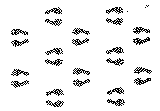 Plate i |
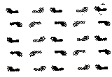 Plate ii |
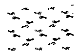 Plate iii |
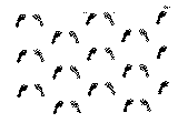 Plate iv |
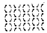 Plate v |
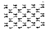 Plate vi |
Copyright © 1984, 1998 International Union of Crystallography
IUCr Webmaster