![[IUCr Home Page]](/iucr-top/logos/iucrhome.gif)
![[Commission Home Page]](/iucr-top/logos/cteach.gif)
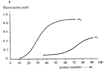
When suitably excited, atoms of every element will emit characteristic radiation whose wavelength is a function of the reciprocal of the square of the atomic number Z of the element. In principle, it is possible to identify the elements in a sample by exciting it and measuring the wavelengths of the characteristic X-rays that are emitted. The efficiency of emission--The Fluorescent Yield--is dependent on atomic number; high with high atomic number and rapidly dropping off as Z drops below about 20 (see Fig. 30).
Increasing the concentration of any element in the sample will result in a proportional increase in the intensity of the fluorescent radiation characteristic of that element. Thus, X-ray fluorescence is simultaneously a qualitative and quantitative technique: ideal for non-destructive analysis of alloys.
In practice the sample is excited by a high intensity beam of X-rays, sometimes monochromatic, sometimes white (or continuous). Not only is the choice of tube target dictated by the type of analysis being done, the correct choice of tube current and potential is just as important.
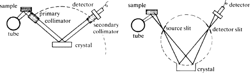
Two typical arrangements for an X-ray spectrometer are shown diagrammatically
in Fig. 31. The heart of the instrument is the crystal analyser.
It is chosen so that one set of planes of exactly known d-spacing is
presented to the fluorescent X-ray beam. The crystal can be rotated so
that ![]() can be varied, and then the Bragg equation
can be varied, and then the Bragg equation
![]() , is applied, d is fixed,
, is applied, d is fixed, ![]() can be measured directly hence the wavelength
can be measured directly hence the wavelength ![]() of the
diffracted X-ray beam can be calculated. The choice of the analysing
crystal is determined by the range of wavelengths which are to be
measured, the length of acceptable counting times, and by the type of
detector that is to be used.
of the
diffracted X-ray beam can be calculated. The choice of the analysing
crystal is determined by the range of wavelengths which are to be
measured, the length of acceptable counting times, and by the type of
detector that is to be used.
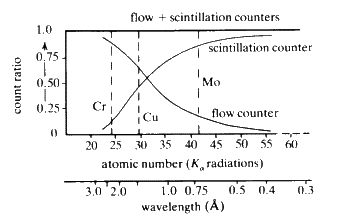
There are at least four well-defined types of counters available commercially.
The choice of counter is determined by the wavelengths of the X-rays to be detected, required counting rates, sensitivity and acceptable background noise.
The combination of flow, proportional and scintillation counter has obvious advantages if a wide range of elements are to be analysed (Fig. 32).
 |
| Geiger | Proportional | Gas Flow | Scintillation | |
| Window | Mica | Mica | Mylar/Al | Be/Al |
| Thickness | 3 mg/cm2 | 2.5 mg/cm2 | 6 |
0.2 mm |
| Position | Radial | Axial | Axial | Radial |
| Filling | Ar/Br | Xe/CH4 | Ar/CH4 | -- |
| Pre-amplifier | unnecessary | |||
| Auto-amplification | 109 | 106 | 106 | 106 |
| Useful range (Å) | 0.5-4 | 0.5-4 | 0.7-10* | 0.1-3 |
| Dead time (Micro seconds) | 200 | 0.5 | 0.5 | 0.2 |
| Max. useful count rate | 2 |
5 |
5 |
106 |
| Cosmic background (c/s) | 0.8 | 0.4 | 0.2 | 10 |
| Resolution % (Fe |
-- | 14 | 15 | |
| Quantum counting efficiency | reasonably independent of |
Copyright © 1981, 1997 International Union of Crystallography
IUCr Webmaster