
Symmetry
L. S. Dent Glasser
1. Simple symmetry operations
The general idea of symmetry is familiar to almost everyone. Formally it can be defined in various ways. The Concise Oxford Dictionary says '1. (Beauty resulting from) right proportion between the parts of the body or any whole, balance, harmony, keeping. 2. Such structure allows of an object's being divided by a point or line or plane or radiating lines or planes into two or more parts exactly similar in size and shape and in position relative to the dividing point, etc., repetition of exactly similar parts facing each other or a centre, ... '.
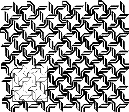
The second of the definitions is the one that relates most closely to crystallography and thus concerns us here, but I have also included the first because it seems to me to express just why the subject is both satisfying and enjoyable. Symmetry and art go hand in hand, as in Fig. 1.1. However, the symmetry of Fig. 1.1 is much more complicated than appears on first sight, so we will begin by considering something rather simpler.
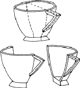
A teacup will do for a start (Fig. 1.2). This is an example of an object that can be divided into two parts by a plane. Since the two parts are mirror images of one another, this symmetry element is called a mirror plane. Operation of this element on one half of the teacup generates the other: if a half teacup is held with its sliced edge against a mirror, the appearance of the whole is regenerated. Teacups are rarely sliced in real life (although it was done in the cartoon version of 'Alice in Wonderland'), but you could try it out with an apple or a pear. If the two similar parts produced have no symmetry remaining, as in the case of the teacup, they are called asymmetric units.
 |
Biological objects such as flowers frequently show symmetry. The person - hereafter referred to as 'it'![]() - shown in Fig. 1.3a also has a mirror plane, provided it stands and parts its hair in the middle (and that we ignore its internal organs). Each half of the figure is an asymmetric unit. Moving an arm or leg destroys the symmetry and the whole figure can then be treated as an asymmetric unit. We will use this little person, both with and without its mirror plane, to illustrate further symmetry elements, and to build more complicated groups.
- shown in Fig. 1.3a also has a mirror plane, provided it stands and parts its hair in the middle (and that we ignore its internal organs). Each half of the figure is an asymmetric unit. Moving an arm or leg destroys the symmetry and the whole figure can then be treated as an asymmetric unit. We will use this little person, both with and without its mirror plane, to illustrate further symmetry elements, and to build more complicated groups.
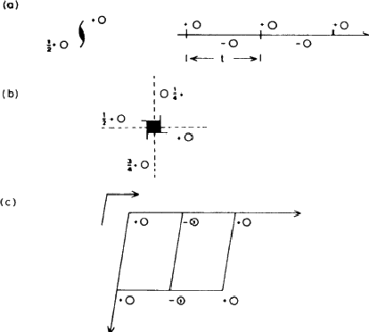
If the figure holds hands with its identical twin, as in Fig. 1.3b, the group formed no longer has a mirror plane. On the other hand rotating the group through 180![]() about an axis (indicated in the diagram) brings each figure into coincidence with its twin. This group has an axis of rotation, twofold in this case because the operation has to be performed twice before each figure returns to its original position. Fig. 1.3c shows how a different method of holding hands produces a group that combines mirror planes with a twofold axis; in Fig. 1.3d identical triplets demonstrate a threefold axis. (Can you identify a fourfold axis in Fig. 1.1? Does it have any twofold axes or mirror symmetry?)
about an axis (indicated in the diagram) brings each figure into coincidence with its twin. This group has an axis of rotation, twofold in this case because the operation has to be performed twice before each figure returns to its original position. Fig. 1.3c shows how a different method of holding hands produces a group that combines mirror planes with a twofold axis; in Fig. 1.3d identical triplets demonstrate a threefold axis. (Can you identify a fourfold axis in Fig. 1.1? Does it have any twofold axes or mirror symmetry?)
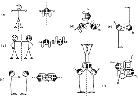 |
Isolated objects or groups of objects may show any number of mirror planes and any kind of axis; the symmetry of an infinite array of identical groups, such as is found in a crystal, is limited by having to pack the units together in three dimensions. This limitation means that in crystallography only centres of symmetry (Fig. 1.3e), mirror planes, two-, three-, four- and sixfold and the corresponding inversion axes are encountered. An inversion axis involves rotation plus inversion through a point; Fig. 1.3f represents a fourfold inversion axis, rotation through one fourth of a revolution being followed by inversion through a point in the middle of clasped hands. A onefold inversion axis is equivalent to a centre of symmetry (Fig. 1.3e) and a twofold inversion axis to a mirror plane. (This last equivalence is important in other contexts because it established a mirror plane as a twofold symmetry operator.)
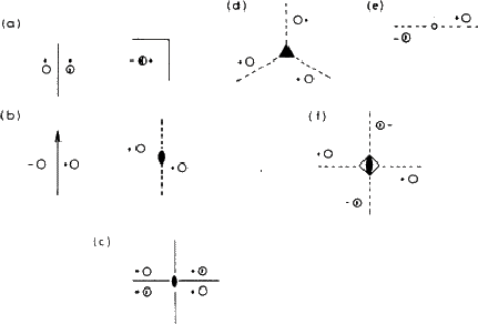
It is not very convenient to illustrate symmetry elements in the way that we have just used: rather than drawing little people we use circles to represent asymmetric units: conventionally an open circle represents a right-handed unit and a circle with a comma in its mirror image or enantiomorph (i.e. a left-handed unit). Fig. 1.4 shows the same groups as Fig. 1.3, represented in this formal, shorthand way.
 |
Even this is inconvenient in written text, in which mirror planes are given the symbol m, while axes and the corresponding inversion axes are referred to as ![]() . The symbol 1 (for a onefold axis) means no symmetry at all, while the corresponding inversion axis (
. The symbol 1 (for a onefold axis) means no symmetry at all, while the corresponding inversion axis (![]() ) is equivalent, as already remarked, to a centre of symmetry.
) is equivalent, as already remarked, to a centre of symmetry.
2. Combination of symmetry elements in finite groups
The complete symmetry displayed by an isolated object or group of objects is its point group , there being always at least one point common to all the symmetry elements. We have already met such a collection of symmetry elements in Figs. 1.3c and 1.4c, comprising two mirror planes intersecting in a twofold axis. Note that no single one of these elements can be left out of the group, because the presence of any two creates the third. This being so, two of the elements are sufficient to define the whole, and this particular point group is normally given the short symbol mm, rather than the full symbol 2mm or mm2.
Similarly, three mirror planes meeting in a threefold axis (Fig. 2.1a) are adequately represented by 3m. The full symbol 3mmm is not needed because two of the 'm 's are redundant, being created by the action of the threefold axis on the other one. Fig. 2.1b shows a mirror plane perpendicular to a twofold rotation axis; this is given the symbol 2/m, the '/' implying 'perpendicular to'. (Note that the combination produces a centre of symmetry at the point where the rotation axis intersects the mirror plane.)
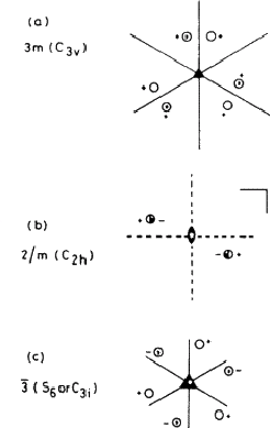 |
This system of nomenclature, which is the one most often used in crystallography is largely self-explanatory, and with very little practice one can draw the appropriate collection of symmetry elements and asymmetric units for any symbol. There is also an older system in use which is not so convenient for our purposes; in Fig. 2.1 examples of this Schoenflies notation are given in brackets after the crystallographic (Hermann-Mauguin) notation: a concordance between the two is given in Table 1. A major difference is that the operator that we have called an inversion axis ![]() (= n-fold rotation plus inversion through a point) is replaced by an alternating axis Sn (= rotation plus reflection across a plane) in the Schoenflies notation. Moreover, as Fig. 2.1c shows, n may change: a threefold inversion axis corresponds to a sixfold alternating axis. Inconvenient though this may be, it does illustrate that the distinction between three- and sixfold symmetry is sometimes a matter of definition, and therefore arbitrary.
(= n-fold rotation plus inversion through a point) is replaced by an alternating axis Sn (= rotation plus reflection across a plane) in the Schoenflies notation. Moreover, as Fig. 2.1c shows, n may change: a threefold inversion axis corresponds to a sixfold alternating axis. Inconvenient though this may be, it does illustrate that the distinction between three- and sixfold symmetry is sometimes a matter of definition, and therefore arbitrary.
There are thirty-two distinct combinations of the crystallographic symmetry operations that relate to finite groups, and thus there are thirty-two point groups or crystal classes; crystals often reveal the class to which they belong through the symmetry of their external forms. These crystal classes are conveniently grouped into systems according to the restrictions placed on the shape of the unit cell (see next section) by the symmetry of its contents. This is summarised in Table 1.
| System | Characteristic symmetry | Unit cell shape | Lattice types | Classes |
| Triclinic | None | P | ||
| Monoclinic | One twofold axis (2 or |
P,C (or A) | ||
| 2/m(C2h) | ||||
| Orthorhombic | Three mutually perpendicular twofold axes | P,C, | 222(D2), mm2(C2v) | |
| (or A orB) | mmm(D2h) | |||
| I,F | ||||
| Tetragonal | One fourfold axis | P,I | ||
| 422(D4), 4nn(C4v) | ||||
| Trigonal | One threefold axis | P<R | 3(C3), 3(S6,C3i), 32(D3) | |
| 3m(C3v), 3m(D3d) | ||||
| Hexagonal | One sixfold axis | P | ||
| Cubic | Four threefold axes (along body diagonals of a cube) | a=b=c | P,I,F | 23(T), m3(Th), 432(O) |
| 43m(Td), m3m(Oh) |
* That is, no restrictions.
3. Symmetry elements in arrays
If you look back at Fig. 1.1, you will see that it combines elements of symmetry with a repeating pattern. We call such a repeating pattern of motifs an array; the smallest convenient parallelogram that can be repeated without change of orientation to produce the pattern is called the unit cell. A two-dimensional unit cell is outlined in Fig. 1.1; note that while the choice of origin is somewhat arbitrary the shape is not. (Check this by identifying other ways of defining the repeating unit.)
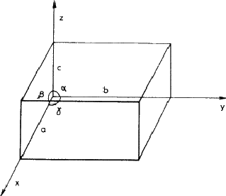
In a three-dimensional array, such as a crystal, the unit cell is a parallelipeped defined by intercepts a, b, c on three axes (x, y, z ) and the angles between them, ![]() ,
, ![]() ,
, ![]() , as shown in Fig. 3.1. If the contents have no symmetry or a centre of symmetry only, the unit cell can have this quite general shape; more symmetrical cell contents restrict the values of the interaxial angles and the relative sizes of the edges in the manner given in Table 1. Thus a single direction of twofold symmetry (monoclinic system) makes two of the angles into right-angles but places no restrictions on the third or on the edge dimensions; at the other extreme, cubic symmetry produces a cell whose edges are all equal and whose angles are all 90
, as shown in Fig. 3.1. If the contents have no symmetry or a centre of symmetry only, the unit cell can have this quite general shape; more symmetrical cell contents restrict the values of the interaxial angles and the relative sizes of the edges in the manner given in Table 1. Thus a single direction of twofold symmetry (monoclinic system) makes two of the angles into right-angles but places no restrictions on the third or on the edge dimensions; at the other extreme, cubic symmetry produces a cell whose edges are all equal and whose angles are all 90![]() (i.e. a cube!).
(i.e. a cube!).
 |
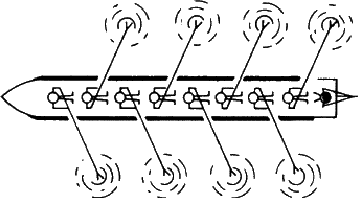
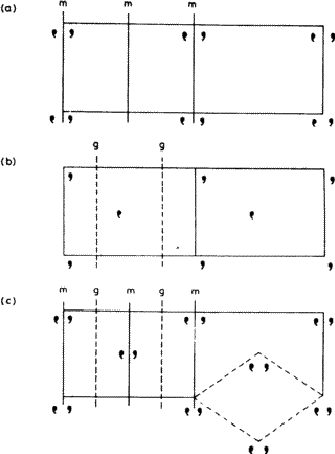
An array can have any of the symmetry elements that we have discussed already, including no symmetry at all (Fig. 3.2), and it can also have additional types of symmetry not possible in finite objects. Consider Fig. 3.3 which shows an aerial view of a boat rowed by eight crew; provided that they have been well coached they present a symmetrical appearance, but it is not one that can be exactly described by any of the symmetry elements introduced so far. It is obviously related to a mirror plane, but in Fig. 3.3 each rower is the mirror image of one rowing immediately in front or behind. Any figure is related to the next by moving one place along the boat and then reflecting across a mirror plane. A symmetry operation of this type is called - very descriptively - a glide plane. Because a glide plane combines the operation of reflection with that of translation it occurs only in extended arrays.
An analogous operation combining rotation and translation is called - equally descriptively - a screw axis. As an actual example of an object possessing this type of symmetry, a bolt is really better than a screw, since most screws taper to a point, but the action of driving a screw - or using a corkscrew! - illustrates very vividly the operation of a screw axis. Other familiar objects having screw axes are spiral staircases, springs, and some climbing plants. Formal examples are shown in Fig. 3.4, together with a formal representation of a glide plane.
 |
 |
 |
The general symbol for a screw axis is Nn, where N is the order (2, 3, 4 or 6) of the axis, and n /N the translation distance expressed as a fraction of the repeat unit. Thus, 41, shown in Fig. 3.4b, means that the asymmetric unit moves ![]() of a repeat unit along the axis for each
of a repeat unit along the axis for each ![]() of a revolution about that axis. Glide planes are symbolised by a letter indicating the direction of the glide: the letters a, b and c mean that the direction of glide is parallel to the a, b and c axes, respectively, while n and d refer to glide planes in which the direction of glide is diagonally across a face of the unit cell or along a body diagonal.
of a revolution about that axis. Glide planes are symbolised by a letter indicating the direction of the glide: the letters a, b and c mean that the direction of glide is parallel to the a, b and c axes, respectively, while n and d refer to glide planes in which the direction of glide is diagonally across a face of the unit cell or along a body diagonal.
A combination of parallel translational and non-translational symmetry elements produces an interesting effect on the way in which the pattern repeats. Consider Fig. 3.5. The pattern in 3.5a contains mirror planes: note that two mirror planes are associated with each repeat unit across the page. The pattern in 3.5b is based on a similar motif related by glide planes (g ); again two are associated with each repeat unit across the page. In 3.5c there are parallel mirror and glide planes, and as a result the grouping of motifs at the centre of the rectangular cell is identical with that at the corners. Such a pattern is called centred, while those of 3.5a and 3.5b are said to be primitive . It is always possible to define a smaller primitive cell for a centred pattern, such as the diamond-shaped cell outlined at the lower right of 3.5c. However, this is not normally done, partly because such a cell is a less convenient shape, but more importantly because its axes no longer bear the correct relationship to the symmetry elements of the pattern.
 |
4. Space groups
Just as the non-translational symmetry elements can be combined into point group symbols that describe the symmetry of finite groups, so the symmetry of infinite arrays can be summarized and symbolized. The addition of translation greatly increases the possibilities, so that instead of the 32 point groups 230 space groups are needed to describe the symmetries of infinite arrays. A complete list of these, with descriptions, is given in International Tables for X-ray Crystallography (see Section 5). All that will be attempted here is to try to give some idea of what a space group symbol means and how to interpret it.
Typical space group symbols are: ![]() , C2/m, Ibca,
, C2/m, Ibca, ![]() , Fm3m, P212121. You will notice that they all begin with a capital letter. This gives the lattice type , which tells you whether the unit cell is primitive or centred. P means primitive, A, B , or C means centred on the face perpendicular to the a, b or c axis, respectively, F means centred on all the faces, I means body centred - centred in the middle of the cell (from the German, innenzentriert ) - and R means rhombohedral, which is a special type of centring unique to the trigonal system. The group of symbols that follow give you the crystal class, and hence the system. Thus in
, Fm3m, P212121. You will notice that they all begin with a capital letter. This gives the lattice type , which tells you whether the unit cell is primitive or centred. P means primitive, A, B , or C means centred on the face perpendicular to the a, b or c axis, respectively, F means centred on all the faces, I means body centred - centred in the middle of the cell (from the German, innenzentriert ) - and R means rhombohedral, which is a special type of centring unique to the trigonal system. The group of symbols that follow give you the crystal class, and hence the system. Thus in ![]() , the symbol
, the symbol ![]() tells you that the system is triclinic (see Table 1). Likewise C2/m belongs to class 2/m, which you can see from Table 1 is monoclinic.
tells you that the system is triclinic (see Table 1). Likewise C2/m belongs to class 2/m, which you can see from Table 1 is monoclinic. ![]() and Fm3m are equally easy to assign to the trigonal and cubic systems, respectively. Ibca presents slightly more of a problem; the symbols b, c and a refer to glide planes, as explained in the previous section. To find the crystal class, simply replace any translational symmetry element by the equivalent non-translational element: this rule holds for both glide planes and screw axes. Thus Ibca belongs to class mmm, and is orthorhombic; the last example, P212121, belongs to class 222 and is also orthorhombic. The symbol also gives the positions of the various symmetry elements. Just as mmm implies mirror planes perpendicular to the three mutually perpendicular axes of the orthorhombic system, so Ibca tells us that in the body-centred array there are b glide planes perpendicular to the x axis, c glides perpendicular to y and a glides perpendicular to z.
and Fm3m are equally easy to assign to the trigonal and cubic systems, respectively. Ibca presents slightly more of a problem; the symbols b, c and a refer to glide planes, as explained in the previous section. To find the crystal class, simply replace any translational symmetry element by the equivalent non-translational element: this rule holds for both glide planes and screw axes. Thus Ibca belongs to class mmm, and is orthorhombic; the last example, P212121, belongs to class 222 and is also orthorhombic. The symbol also gives the positions of the various symmetry elements. Just as mmm implies mirror planes perpendicular to the three mutually perpendicular axes of the orthorhombic system, so Ibca tells us that in the body-centred array there are b glide planes perpendicular to the x axis, c glides perpendicular to y and a glides perpendicular to z.
The page of International Tables describing Pnma is reproduced in Fig. 5.1, from which it can be seen that the total collection of symmetry elements include many that are not listed in the space group symbol. Only the essential elements are given in the symbol; redundant ones are omitted, just as they are from point group symbols.
5. International Tables for X-ray Crystallography, Volume I
International Tables for X-ray Crystallography contain a great deal of information concerning various aspects of crystallography, and the first volume deals with symmetry. Among other things, it introduces symmetry considerations in more detail and at a more advanced level than can be given here. It also lists information about all the space groups, and it is this that we will consider now. Fig. 5.1 reproduces a typical page from the space group listings, and we will use it to explain some of the important features.
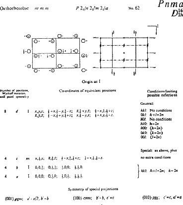 |
The space group symbol - Pnma - is given in bold type at the top of the page, together with the equivalent Schoenflies symbol. Replacing the translational elements n and a by the non-translational equivalent m gives crystal class mmm, system orthorhombic: this information is also given at the top of the page. On this same line are: (1) the full symbol P 21/n 21/m 21/a (which includes redundant twofold screw axes parallel to a, b and c created by the interaction of the mirror and glide planes) (2) the space group number, 62. The space groups are listed in a logical sequence in increasing symmetry of their crystal classes, beginning with No. 1, P1, which has no symmetry at all, and ending with the highly symmetric cubic group Ia3d, No. 230.
Immediately below this top line are two diagrams representing the space group in terms of asymmetric units (on the left) and as a collection of symmetry elements (on the right). They are projected onto the page down the z axis, with the y axis running horizontally from left to right across the page and the x axis downwards. The space group symbol tells us that there is an n-glide plane perpendicular to the x axis, a mirror plane perpendicular to the y axis and an a-glide plane perpendicular to the z axis (i.e. parallel to the plane of the paper); these appear on the right-hand diagram as dot-dash lines, heavy solid lines, and a right-angled line with an arrow, respectively. (The arrow shows the direction of the glide - along a; the small figure ![]() indicates that the glide plane is c /4 above the plane of the diagram.) The redundant twofold screw axes also appear, and a number of centres of symmetry are created.
indicates that the glide plane is c /4 above the plane of the diagram.) The redundant twofold screw axes also appear, and a number of centres of symmetry are created.
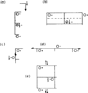
The effect of these symmetry operations can be traced in the left hand diagram. The effect of the mirror plane is particularly easy to see (refer back to Fig. 1.4). After you have found this, look for the effect of the glide planes and screw axes; a key is given in Fig. 5.2. All the reflection planes occur in groups, separated by half a cell edge; here they are ![]() and
and ![]() of the way along because the origin has been chosen at a centre of symmetry (this has computational advantages).
of the way along because the origin has been chosen at a centre of symmetry (this has computational advantages).
 |
The remaining feature of the page that concerns us here is the list of coordinates of equivalent positions. An asymmetric group placed at random in the cell (at x, y, z, for example, a position represented by the open circle at '+' in the top left hand corner of the left hand diagram) must be matched by seven other groups, a total of eight in all. Applied to a crystal structure, this means that an atom that occurs in such a general position must be one of a total of eight similar atoms in the unit cell; this can be very helpful in deciding chemical formulae. In the Tables, the coordinates corresponding to this general position are listed first: 8 is the number of equivalent positions, d is simply a letter assigned as a convenient means of referring to the set, and 1 shows that the site has no symmetry.
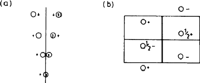 |
Suppose now that the group is moved from x, y, z to x , ![]() , z - that is, onto the mirror plane (Fig. 5.3). This brings it into coincidence with its mirror image, and reduces the number of groups to four. This situation is summarised in the line beginning 4c ...; the symmetry of the site is now m, and there are only four equivalent positions instead of eight. The remaining two lines show the effect of selecting a position on one or other of the centres of symmetry. We make no use here of the rest of the information on the page.
, z - that is, onto the mirror plane (Fig. 5.3). This brings it into coincidence with its mirror image, and reduces the number of groups to four. This situation is summarised in the line beginning 4c ...; the symmetry of the site is now m, and there are only four equivalent positions instead of eight. The remaining two lines show the effect of selecting a position on one or other of the centres of symmetry. We make no use here of the rest of the information on the page.
This final paragraph gives a very brief illustration of one practical use of such symmetry information. Suppose that a metal sulfate, MSO4, crystallizes in this space group with four formula units per cell. The four M and S atoms must lie on one of the positions, a, b or c; the sulfur atom forms part of a sulfate group. SO4 groups are tetrahedral, tetrahedra don't have centres of symmetry but do have mirror planes: therefore the sulphur atom must occupy position c, on the mirror planes (as also must two of the oxygen atoms attached to it). Combining this information with a knowledge of bond lengths should enable a trial structure to be worked out.
- ...'it'
- Thus avoiding any sexist implications!